Eerst je kabel flink terugstellen met de spanner op de kap tot er heel veel speling in zit. Dan de contramoer op je wormwieltje 1/4-1/2 slag losdraaien. Zit achter het puntje van je eitje (kleine voorste kettingkastje achter je ontsteking) of de rubberdop op je linkerkap. Het stukje schroefdraad is dan in- en uit te draaien met een kleine kruiskop, maar een spanningzoeker lukt meestal ook wel. Eerst eens een stukje uitdraaien. Daarna indraaien tot je een beetje weerstand voelt, en ongeveer 1/8-1/4 weer losdraaien. Met de sleutel 10 het contra moertje aandraaien terwijl je met je schroevendraaien het stukje draad tegenhoudt. Koppelingskabel weer strakzetten tot je nog wel wat speling in de handle kunt zien. Je koppeling is nu goed gesteld. Check even of aan het hefboompje van het wormwieltje een veertje zit dat het weer terugtrekt als je het koppelingshandle laat opkomen. (Zit aan binnenkant linkerdeksel.)
Slipt hij daarna nog steeds of komt hij nog steeds niet goed vrij, dan kunnen er een aantal zaken niet in orde zijn:
Versleten platen of veren
versleten wormwiel of als je pech hebt de worm in je linker deksel
kromme koppelingsstift
verpulverd kogeltje in versnellingsas tussen de drukstiftjes
Kromme platen
ingeslagen koppelingshuis.
Als je worm er toch uit is, maak de worm dan even goed schoon en vet hem goed dik in. Met het hefboompje naar beneden in het wormgat steken en omhoog draaien. Dan de kabel erin en dan pas het veertje weer terug. Als het goed is blijft alles dan voldoende hangen om het deksel weer op het blok te monteren en kun je beginnen met afstellen.
Als opvalt dat het kogeltje in je worm er bijna uitgedraaid wordt met afstellen, ben je waarschijnlijk vergeten het kleine kogeltje tussen de 2 drukstiften te monteren.
Nieuw wormpje monteren:
Je nieuwe setje kun je op 4 verschillende manier in elkaar zetten. 1 Ervan is maar goed. Het armpje moet de opening omlaag hebben wijzen en in gemonteerde helemaal ingedraaide toestand niet ver naar benden wijzen. Eigenlijk moet hij horizontaal staan, dan is het goed.
Er zit ook een keerring bij die je op 2 manieren erop kunt doen. 1 Manier is maar goed. als je je worm in de kap draait, moet de lip soepel het gat in gaan en niet de boel juist blokkeren.
Klinken doe je door eerst een boutje in de worm te draaien. Dan steunt niet het teflondeel op je ondergrond, maar de bout. Vaak wordt het teflon al kapot geslagen voor de worm gemonteerd kan worden. Klinken is nodig zodat de arm op de worm blijft zitten. als je eenmaal hebt uitgevogeld hoe alles erop moet, dan kun je het uitstekende stukje plat slaan of er een snelle laspunt op zetten. Let op als je de boel plat slaat, dat je de kogel er al in hebt zitten. anders wil die vaak niet meer omdat het gat ook een beetje dichtgeslagen wordt.

Paarse veertjes:
Bij 50cc.nl zijn DT80LC veertjes te koop die zo in je FS1 passen. Ze zijn een pietsje sterker dan onze groene en dat kan net genoeg zijn om een koppeling goed aan te laten grijpen op een snellere brommer. Nummer 20501 is wat je zoekt.
3-plaatskoppeling:
Sommigen zijn erg handig met de draaibank en kunnen de grondplaat en drukplaat zover afdraaien dat er 3 gevoerde en 2 ongevoerde platen gemonteerd kunnen worden. Let op dat je de schroefjes van de drukveren iets minder ver indraait en daar soms wat tussen moet doen.
Aanpassen kap voor RD worm:
marco schreef:Van het engelse forum geleend:
I've finally got round to finishing the clutch worm repair that I started a thread about some time ago. The pictures were lost on the old thread during the site facelift, so I thought I'd start from the begining in case the repair method is useful to someone else.
The clutch mechanism worked on my DX, but when I checked it, the worm threads in the case were almost worn away and failure was going to happen soon. I asked on here and searched on the internet for a solution and initially the only way forward seemed to be to source another side case. Then I spotted that the RD50 and FS1E clutch mechanisms were very similar, but the RD50 looked a better design as both parts of the worm mechanism can be replaced.
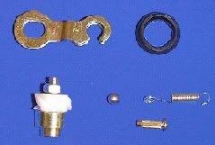
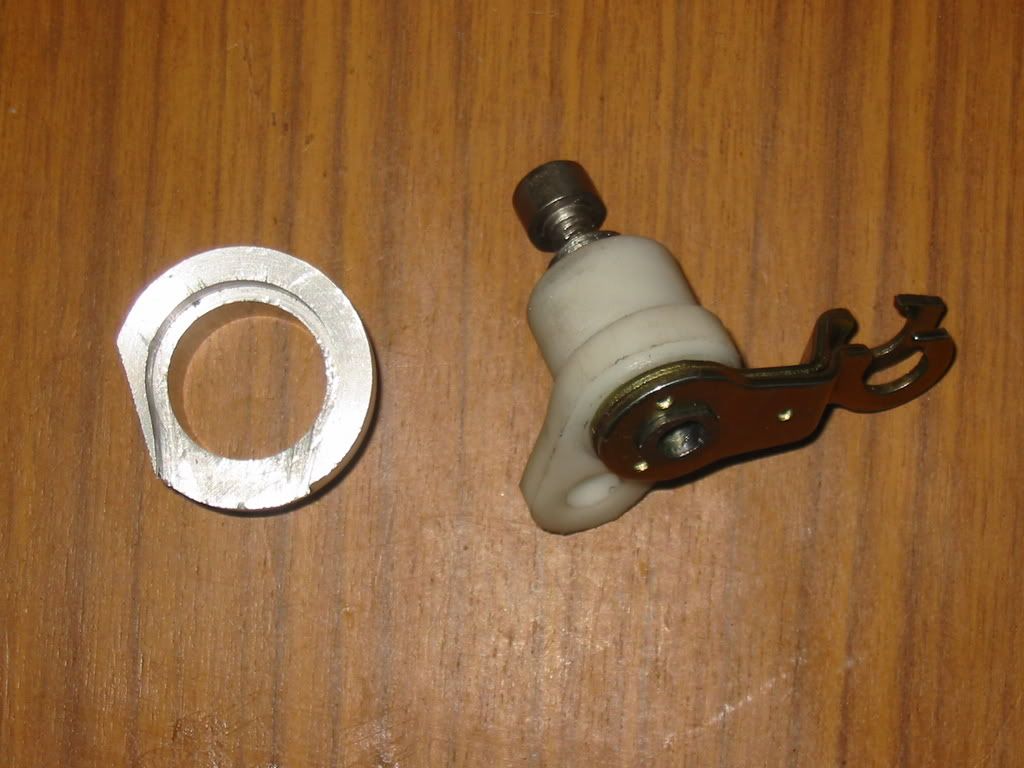
FS1E parts.
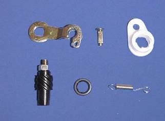
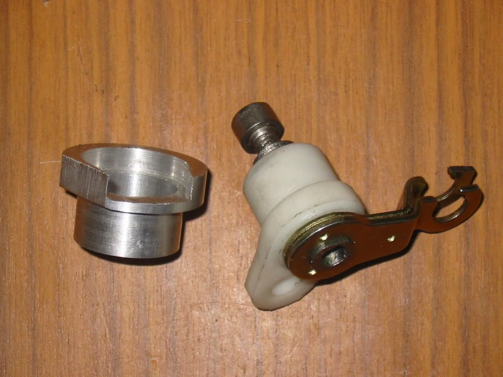
RD50 Parts
I decided to try and fit the RD50 parts to my FS1E side case, so I ordered a pattern set and tried a few things out. I won't go into all the trials and errors, thats all in the original thread. I'll just list here what you need to do to make it work.
Step 1 Order an RD50 clutch worm set.
You can get a pattern set for a few pounds as I did first time round, but genuine isn't much more and the worm thread quality is better. The parts you need are:
rd50 worm housing353-16396-00
rd50 worm screw241-16341-01
rd50 arm 451-16342-00
rd50 seal 93104-11028
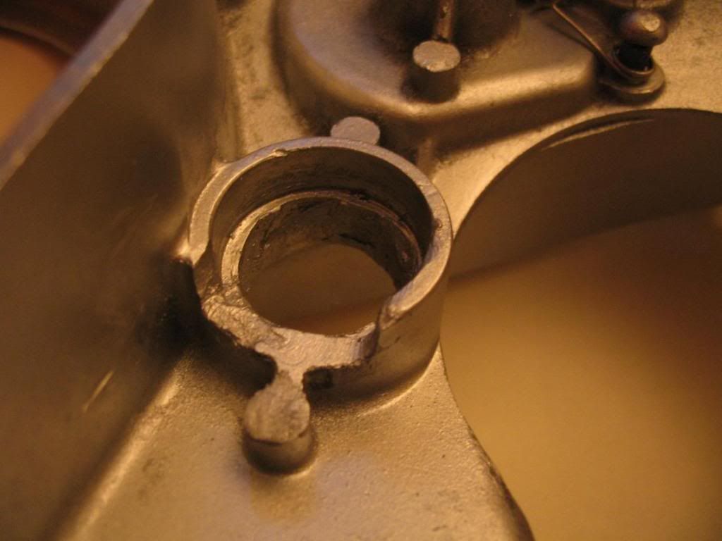
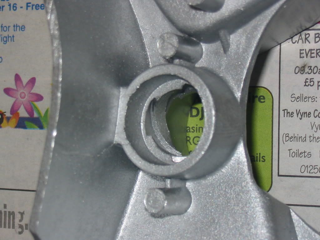
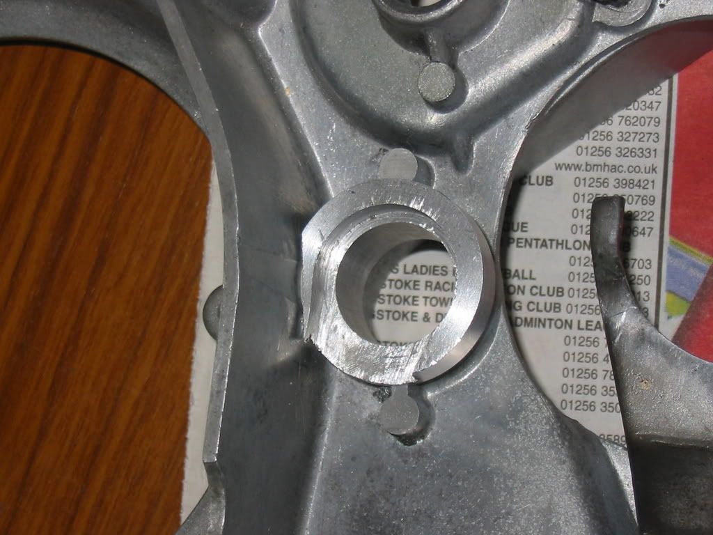
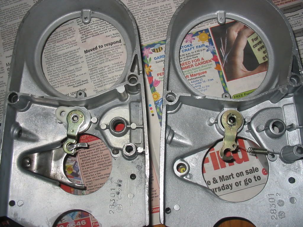
Step 2 Get the side case machined.
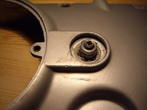
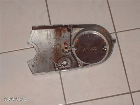
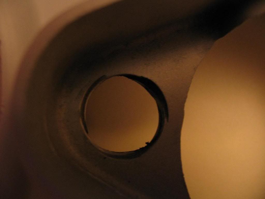
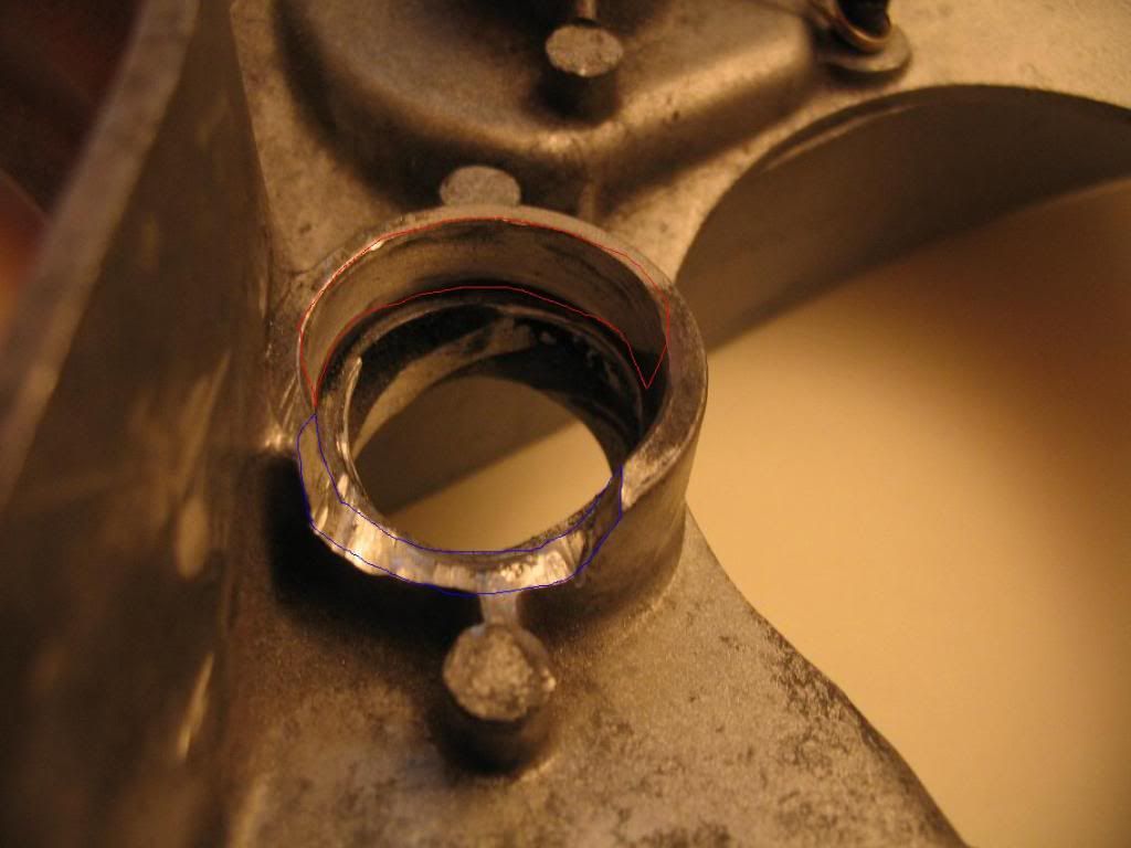
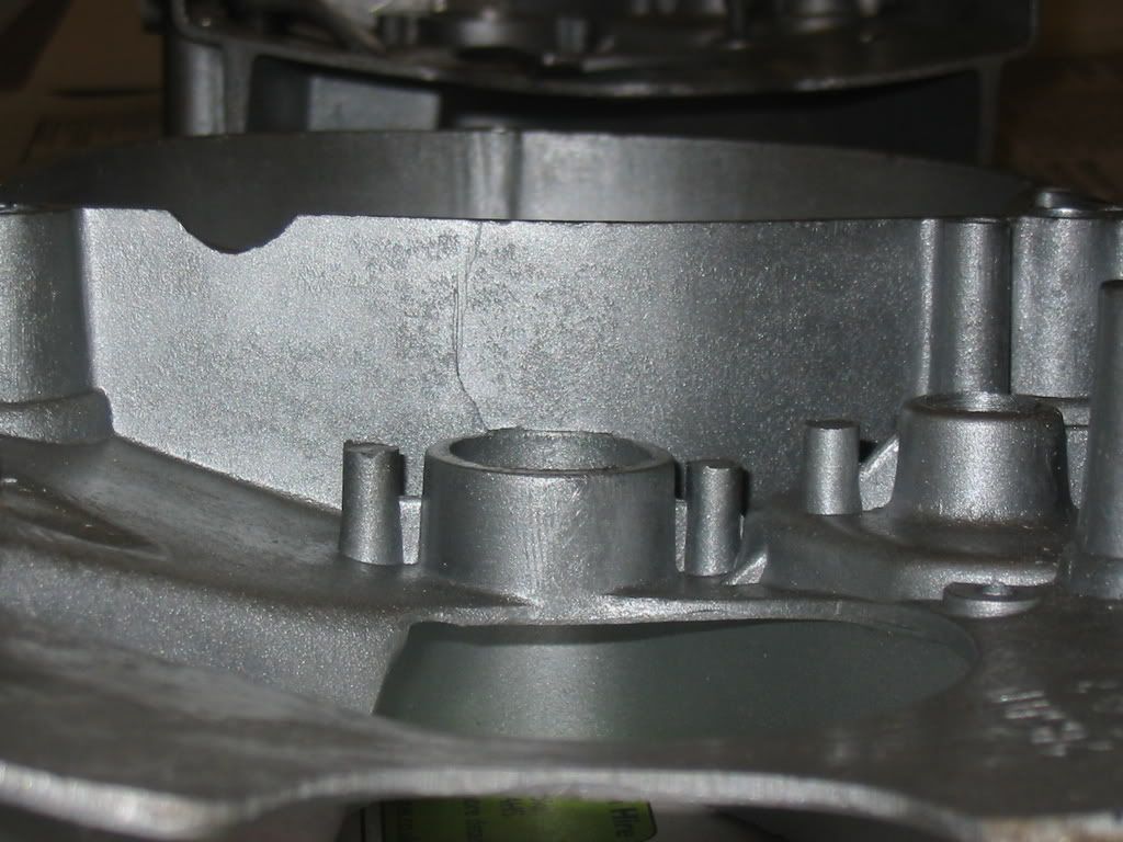
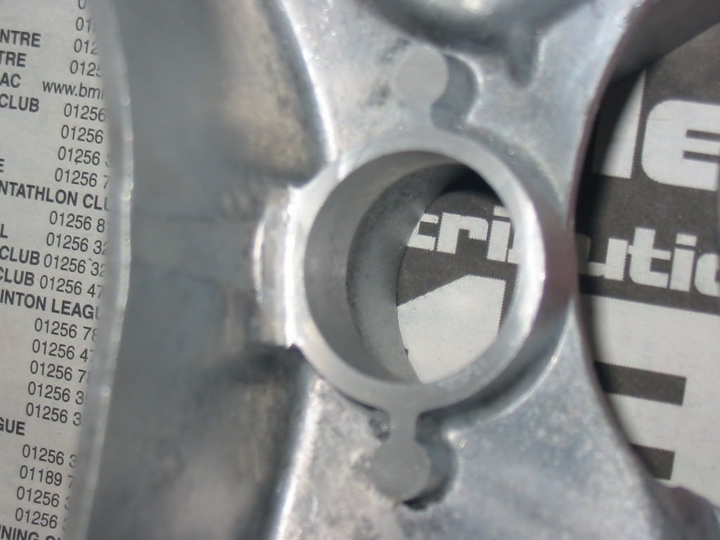
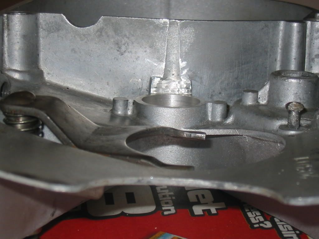
All remains of the old worm thread have to be removed by boring out to a diameter of about 22.4mm. It is also necessary to machine back the cylindrical bit and the 2 casting thingys that stick out by removing 6mm. You should end up with a cylindrical bore about 10mm long. The first 2 pictures show a new case, as I don't have any pics of the worn one before machining. The next 2 pictures are post machining.
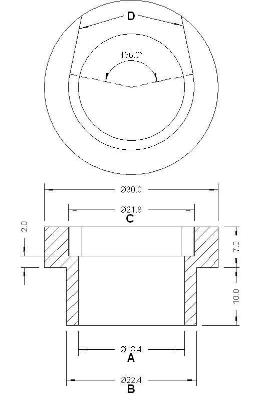
Step 3. Get a bush made.
An aluminium alloy bush needs to be made to mate the RD50 plastic worm housing to the Fizzy side case. See sketch below. However some of the dimensions are only as a guide. You will need to measure your machined case and your worm housing to get them correct. In the sketch, dimension A needs to be a tight fit on the worm housing. Dimension B needs to be a sliding fit in the side case. Dimension C and cut lines D need to be a clearance fit on the worm housing. All other dimensions can be as written
Step 4 File a flat on the bush.
A flat has to be filed on one side of the bush to match the casing next to the generator. This has the advantage in that it prevents the bush rotating. The way the worm housing sits in the bush then stops stops the worm housing from rotating as well.
Exactly where you file the flat is important though. With the worm mechanism assembled the arm should be at 90 degrees to the cable. I did notice that there was a difference between the best position for the pattern and genuine RD50 parts.
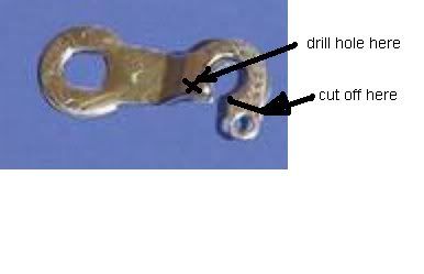
Step 5 Modify the RD50 Clutch arm
The bit the spring is designed to attach to is different from the Fizzy arm and catches on the output shaft, so it needs to be cut off. Then a small hole needs to be drilled to attach the spring like the Fizzy arm.
Step 6 Fit it all together and try it.
At this stage it should all hold together well enough to test on the bike. The RD50 worm has a larger pitch than the Fizzy one. This means that the clutch plates move further apart for a given lever movement and the clutch will feel heavier. I was concerned that the springs would become coil bound, so I initially tried it with the clutch cover removed, but that didn't seem to cause a problem and with a well oiled cable the clutch wasn't noticably heavy.
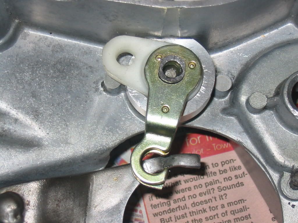
Step 7 Glue the bush in place.
I used loctite 638 retainer. 601 would probably be just as good. Araldite or superglue would probably be adequate. If it was made a tight fit, it may be ok with no glue at all. I machined the bush so that the plastic worm housing was a fairly tight fit and can only just be pushed in by hand.
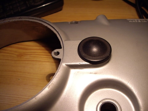
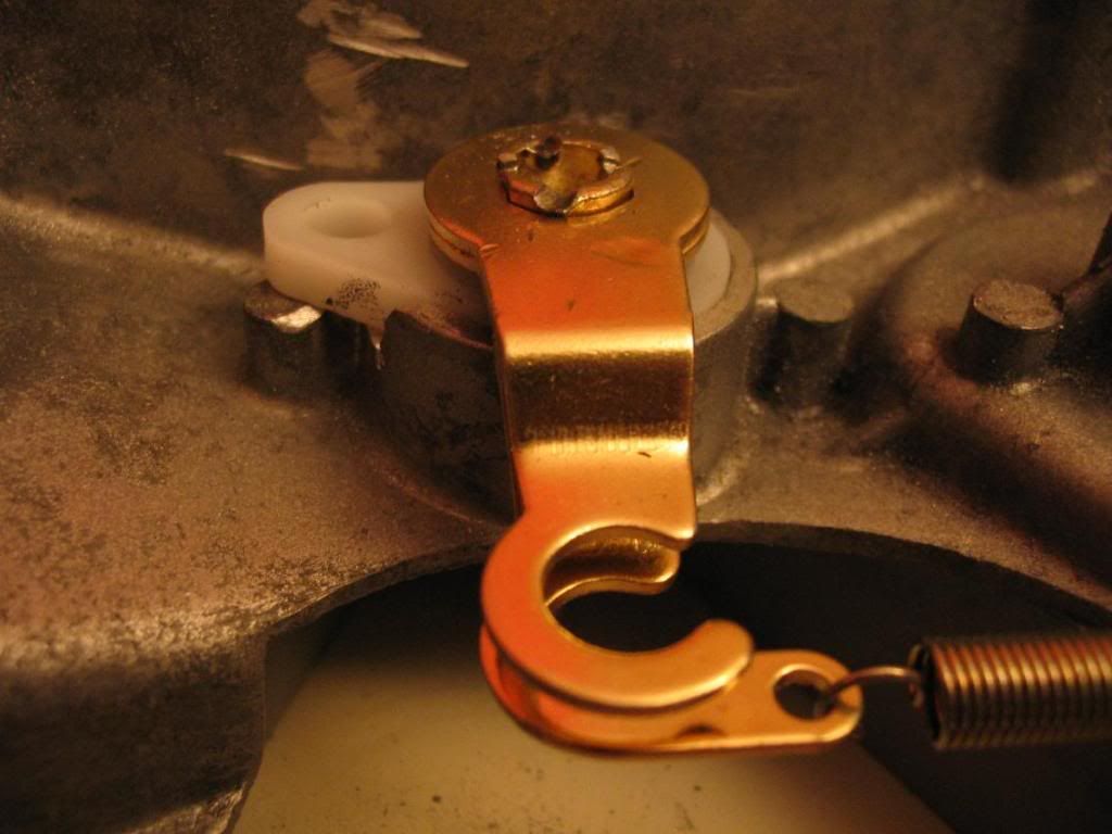
The picture shows the modified casing next to a new pattern case fitted with a standard fizzy arm. This was before I drilled the small hole to fit the return spring. If anyone else has a go please let me know how you get on. Especially with any improvements I'm sure there will be some better ways.
Cheers
Mark C
Of als je geen probleem hebt met wat hand- en kleiwerk:
marco schreef:Deze week bezig geweest om een koppelingsworm van een rd in een versleten koppelingskap te maken.
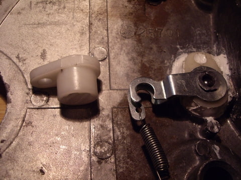
Je moet ongeveer 5mm wegvijlen/slijpen van de hoogte van het orginele alu busje met het draad.
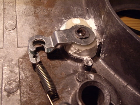
Op de onderste foto bij het rode rondje moet je van het alu niks af vijlen maar een soort pennetje laten staan anders kan het kunstof busje meedraaien.
Ik heb het vast gezet met "sealer" een sterke montagekit van hercuseal.